- 您现在的位置:买卖IC网 > Sheet目录311 > AS5134 PB (ams)BOARD PROGRAM AS5134
�� �
�
�AS5134�
�Datasheet� -� A� p� p� l� i� c� a� t� i� o� n� I� n� f� o� r� m� a� t� i� o� n�
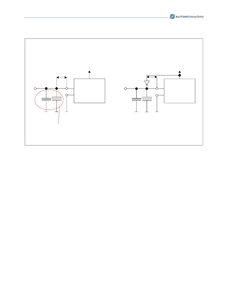
�Figure� 17.� OTP� Programming� Connection�
�Standard� Case�
�Special� Case�
�maximum�
�parasitic� cable�
�inductance�
�V� SUPPLY�
�V� SUPPLY�
�V� zapp�
�L<50nH�
�V� prog�
�PROG�
�V� DD�
�V� zapp�
�L<50nH�
�V� prog�
�PROG�
�V� DD�
�C1�
�100nF�
�C2�
�10μF�
�GND�
�PROM� Cell�
�C1�
�100nF�
�C2�
�10μF�
�GND�
�PROM� Cell�
�Remove� for� normal� operation�
�Note:� The� maximum� capacitive� load� at� PROG� in� normal� operation� is� less� than� 20pF.� However,� during� programming� the� capacitors� C1+C2� are�
�needed� to� buffer� the� programming� voltage� during� current� spikes,� but� they� must� be� removed� for� normal� operation.� To� overcome� this�
�contradiction,� the� recommendation� is� to� add� a� diode� (4148� or� similar)� between� PROG� and� V� DD� as� shown� in� Figure� 17� (special� case�
�setup),� if� the� capacitors� can� not� be� removed� at� final� assembly.�
�Due� to� D1,� the� capacitors� C1+C2� are� loaded� with� V� DD� -0.7V� at� startup,� hence� not� influencing� the� readout� of� the� internal� OTP� registers.�
�During� programming� the� OTP,� the� diode� ensures� that� no� current� is� flowing� from� PROG� (8-8.5V)� to� VDD� (5V).�
�In� the� standard� case� (see� Figure� 17� ),� the� verification� of� a� correct� OTP� readout� can� be� done� either� by� analog� readback� of� the� OTP� reg-�
�ister� or� with� the� aid� of� the� OTP_OK� bit.� The� special� case� setup� provides� only� the� OTP_OK� bit� for� verifying� the� correct� reading� of� the�
�OTP.� Analog� readback� is� not� usable� in� the� special� case� mode,� as� the� diode� pulls� the� PROG� pin� to� V� DD� .�
�The� OTP_OK� bit� can� be� accessed� with� command� #4� (see� Table� 9)� .�
�As� long� as� the� PROG� pin� is� accessible� it� is� recommended� to� use� standard� setup.� In� case� the� PROG� pin� is� not� accessible� at� final�
�assembly,� the� special� setup� is� recommended.�
�8.1.2�
�Programming� Verification�
�After� programming,� the� programmed� OTP� bits� must� be� verified� in� two� ways:�
�Digital� Read� Out� (Mandatory):� After� sending� a� READ� OTP� command,� the� readback� information� must� be� the� same� as� programmed�
�information.� Otherwise,� it� indicates� that� the� programming� was� not� performed� correctly.�
�Note:� Either� “Digital� Verification”� or� “Analog� Verification”� must� be� carried� out� in� addition� to� the� “Digital� Read� Out”.�
�Digital� Verification:� Checking� the� OTP_OK� bit� (0� =� OK,� 1� =� error)�
�i)� At� room� temperature�
�ii)� Right� after� the� programming�
�Analog� Verification:� By� switching� into� Extended� Mode� and� sending� a� READ� ANA� command,� the� pin� PROG� becomes� an� output� sending� an�
�analog� voltage� with� each� clock� representing� a� sequence� of� the� bits� in� the� OTP� register� (starting� with� D61).� A� voltage� of� <500mV� indicates� a�
�correctly� programmed� bit� (“1”)� while� a� voltage� level� between� 2V� and� 3.5V� indicates� a� correctly� unprogrammed� bit� (“0”).� Any� voltage� level� in�
�between� indicates� incorrect� programming.�
�www.austriamicrosystems.com/AS5134�
�Revision� 2.3�
�22� -� 32�
�发布紧急采购,3分钟左右您将得到回复。
相关PDF资料
AS5140 PB
BOARD PROGRAM AS5140
ASDMB-ADAPTER-KIT
ASDMB MEMSPEED P II OSC KIT
ASFLMPLP-ADAPTER-KIT
ASFLMPLP MEMSPEED P II OSC KIT
AT24C01-10SI-1.8
IC EEPROM 1KBIT 400KHZ 8SOIC
AT24C01B-TSU-T
IC EEPROM 1KBIT 1MHZ SOT23-5
AT24C02C-XHM-B
IC EEPROM 2KBIT 1MHZ 8TSSOP
AT24C04AN-10SI-2.7
IC EEPROM 4KBIT 400KHZ 8SOIC
AT24C08B-PU
IC EEPROM 8KBIT 1MHZ 8DIP
相关代理商/技术参数
AS5134-AB
制造商:ams 功能描述:AS5134 Adapter Board
AS5134-ASSU
制造商:AMS 功能描述:ENCODER MAGNETIC ROTARY 8BIT 20SSOP 制造商:AMS 功能描述:ENCODER, MAGNETIC, ROTARY, 8BIT, 20SSOP
AS5134-DB
制造商:ams 功能描述:AS5134 Demo Board
AS5134-PB
功能描述:磁传感器开发工具 AS5134 Progamming Board RoHS:否 制造商:Maxim Integrated 工具用于评估: 接口类型: 工作电压:
AS5134-SS_EK_AB
功能描述:AS5134 - Magnetic, Rotary Position Sensor Evaluation Board 制造商:ams 系列:- 零件状态:有效 传感器类型:磁性,旋转位置 感应范围:360° 接口:串行 灵敏度:- 电压 - 电源:4.5 V ~ 5.5 V 嵌入式:否 所含物品:板 使用的 IC/零件:AS5134 标准包装:1
AS5134-SS_EK_DB
功能描述:AS5134 - Magnetic, Rotary Position Sensor Evaluation Board 制造商:ams 系列:- 零件状态:有效 传感器类型:磁性,旋转位置 感应范围:360° 接口:USB 灵敏度:- 电压 - 电源:5V USB 或 9V 嵌入式:是,MCU,8 位 所含物品:板,线缆 使用的 IC/零件:AS5134 标准包装:1
AS5134-SS_EK_PB
功能描述:AS5000 Programmer, AS5134 - ZIF Socket 制造商:ams 系列:- 零件状态:有效 模块/板类型:ZIF 插口 配套使用产品/相关产品:AS5000 编程器,AS5134 标准包装:1
AS5134-ZSSM
制造商:AMS 功能描述:IC ENCODER RPTARY 20-SSOP